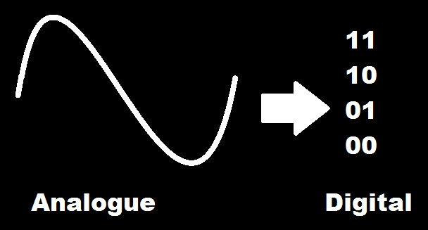
Integrating or Dual Slope ADC
3 Answers
Answer :
Integrating or Dual Slope ADC


•There are basically 4 types of Analog to Digital converter (ADC).
1.Integrating or Dual slope ADC
2.Successive approximation ADC
3.Flash ADC
4.Delta sigma converter
•Dual slope ADC is use for converting analog to digital value.
•This is integrator.
•Dual slope ADC is slow but have high accuracy and have high resistance to noise.
•This method is use in digital multimeter or digital voltmeter.
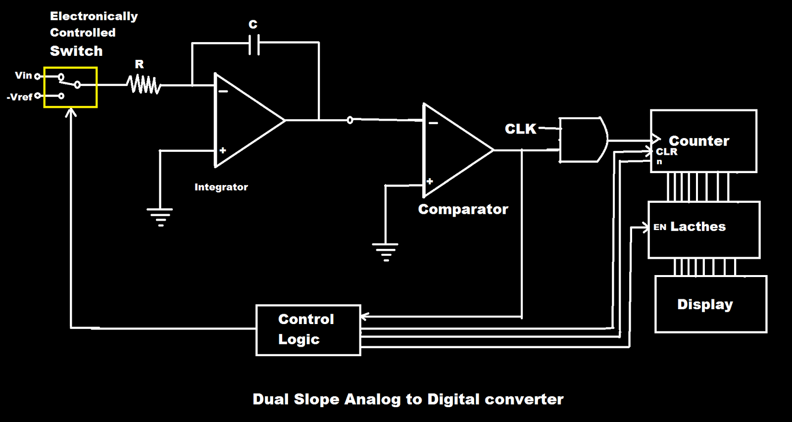
•It is basically have integrator, comparator, control logic, clock, counter and electronically controlled switches.
•Its operation requires two voltage slopes hence it is name as Dual slope.
•The unknown voltage is applied to Vin and Known but with negative polarity voltage is applied to Vref.
•Vin is for fixed amount of time and Vref is applied for variable amount of time.
•One slope (/) is made due to unknown voltage.
•The negative polarity voltage is then applied until it become zero means second slope (\) will form.
•The comparator is use to detect zero crossing.
•Capacitor charges and discharges linearly with a constant slopes.
•T de-int is more than T int because discharging time of capacitor is more than its charging time.
•If T de-int is large means large voltage and if T de-int is less means less voltage.
•When the switch is at Vin position capacitor charges (charging time of capacitor is less).
•And when the switch is at Vref position capacitor discharges (charging time of capacitor is more).
VISIT AT YOUTUBE
BUY BOOKS AT EEE STORE
Answer :
Types of integrating type ADC.
1. Single slope/Voltage to frequency or integrating type A/D converter
2. Dual slope integrating type A/D converter
Single slope/Voltage to frequency or integrating type A/D converter:
Explanation: An analog voltage can be converted to digital form, by producing pulses whose frequency is proportional to the analog voltage. These pulses are counted by a counter for a fixed duration and the reading of the counter will be proportional to the frequency of the pulses and hence, to the analog voltage. Voltage-to-frequency converter In these types of A/D converters, the voltage is converted (by a voltage-to-frequency converter) into a set of pulses repetition rate (or frequency) is proportional to the magnitude of the input. The pulses are counted by an electronic counter similar to the way the number of wavelengths was counted by the time-interval counter in the ramp-type DVM.
or
Dual slope Integration A/D converter
Explanation: In this ADC, an unknown analog voltage and a known reference voltage are converted into equivalent time periods using an integrator, These time periods are measured by the counter. This circuit is called dual slope ADC because the analog voltage and reference voltage are converted to ramp signals of different slopes by the integrator. The dc voltage to be converted by the dual-slope converter, Vin, is fed to an integrator, which produces a ramp waveform output, The ramp signal starts at zero and creases for a fixed time interval, T1 equal to the maximum count of the multiplied by the clock frequency. An 8-bit counter operating at 1 MHz would there by cause T1 to be 8 µs. The slope of the ramp is proportional to the magnitude of Vin. The end of the interval, T1 the carry-out (CO) bit of the ripple counter causes the switch to move to the - VREF position. In this position, a constant current (- VREFI R) begins to discharge capacitor C. The ripple counter is reset to zero there is a Co. The count continues until the zero crossing detector switches state as result of capacitor C being discharged. The counter is stopped by the zero crossing detector, and the resultant count is proportional to the input voltage. In the following derivation it is important to observe that t, is independent of the value of Rand C.
Answer :
Operation: At the start of measurement the counter is reset to zero. So output of flip‐flop is zero. This is applied to the switch control. The switch control now connects input voltage (Vin) to integrator. Integrator now starts integrating the input voltage. That means the capacitor starts charging. Because of this the output of integrator changes from zero value. It courses the zero detector (comparator) to change its stage. That means it provided the high signal to the logic gate thus the opening of logic gate takes place.
When the logic get is opened, the number of clock pulses are passed to the counter . the counter will count these pulses for a certain time t1. After this time the counter is reached to 999. After this 1 is passed to the flip‐flop.
The output of flip‐flop is now 1. This is connected to the control logic. The switch control logic is now changes the position of switch from vin to Vref. So integrator will starts integrating this reference voltage (‐Vref). This will causes the capacitor to starts to discharging. The discharging of capacitor will take place for the time period . The discharging path is having a constant negative slope. This slope is shown in figure. A stage will be reached at which output of integrator becomes zero. This stage is obtained at the end of time period t2. At this instant the output of zero detector gets changed. This will causes the closing of logic gate. Now the pulses from clock are not allowed to pass towards the counter. The counting operation is completed. Then the data from counter is passed to the digital readout for display purpose.