1 Answer
Answer :
Circuits with capacitive reactance X C alone.
Capacitive reactance X C values in series.
There is no resistance or inductive reactance only capacitive reactance is there.
Let two capacitive reactances are connected in series.
The 100 volts A C voltage is applied.
The voltage across capacitive reactance X C 1 is V 1 is equal to Current I into X C 1.
The voltage across capacitive reactance X C 2 is V 2 is equal to current into X C 2.
The current I can be find by Ohm's law.
The phasor diagram shows series current I horizontal because it is taken as reference phasor.
Series current I is taken as reference phasor because same current flowing through both the capacitive reactances.
The voltage across capacitive reactance lags the capacitive charge and discharge current I by 90 degree.
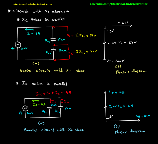
Now capacitive reactances in parallel.
Capacitive current I C values in parallel.
Let two capacitive reactances are connected in parallel.
100 volts A C voltage source is applied.
The current I T can be find by Ohm's law.
The total current I T is equal to I 1 plus I 2.
The current I 1 is equal to voltage V A upon X C 1.
Current I 2 is equal to voltage V A upon X C 2.
The phasor diagram shows the voltage V A as reference phasor.
Voltage V A is common voltage to both X C 1 and X C 2 hence it is taken as reference phasor and horizontal in phasor diagram.
The total current I T leads voltage V A by 90 degree.